


Vertical Cryogenic Liquid Storage Tank are the industry-standard configuration for large-scale stationary storage of liquefied industrial gases. Their tall, cylindrical shape optimizes footprint, leverages hydrostatic pressure for pumping, and is engineered for structural efficiency, making them the preferred choice for air separation unit (ASU) product storage, LNG peak-shaving, and major user bulk installations.
The Default Choice: Why Industry Stands Them Up
When you picture the tank farm of an air separation plant or the backup storage at a major hospital, you're almost certainly picturing vertical cryogenic storage liquid tank. There's a reason this shape is the default. I'm a civil engineer specializing in tank design, and the vertical cylinder is a love letter to efficiency. It starts with land use. A vertical tank occupies a small circle. You can pack immense volume into a limited plot. More importantly, it's about head pressure. The weight of the liquid column itself-the hydrostatic head-provides natural pressure at the pump inlet at the bottom. This Net Positive Suction Head (NPSH) is a gift. It means we can use simpler, more robust pumps and drastically reduce the risk of cavitation, which is the archenemy of any pump, especially one handling -186°C liquid nitrogen. For high-volume, continuous transfer operations, this inherent pressure benefit isn't just nice; it's foundational.
- Fighting the Invisible Forces: Wind, Seismic, and Slosh
But elegance invites unique challenges. A tall, slender vessel is a sail. Wind load calculations aren't an afterthought; they're a primary design driver. The outer shell isn't just a weather cover; it's a structural element braced against lateral forces. The anchor bolt chair-the massive ring of bolts that ties the tank to its foundation-is designed for overturning moments, not just weight. In seismic zones, the analysis gets beautifully complex. You're not just analyzing a static vessel; you're analyzing a sloshing liquid. During an earthquake, the liquid inside wants to slosh back and forth. This dynamic "sloshing load" imposes huge, rhythmic forces on the roof and shell. We model this, sometimes adding internal baffles (though rare in cryogenics due to thermal stress) or specifically designing the roof-to-shell connection to handle it. The tank becomes a giant, liquid-filled tuning fork, and our job is to ensure its natural frequency doesn't match the earthquake's, and that it can survive the resonance if it does.
- The Hierarchy of Access: Grade-Level Guts and High-Aloft Brains
The vertical design creates a natural, and smart, separation of functions. All the dirty, noisy, serviceable parts-the pumps, the main liquid valves, the vaporizers-are clustered at grade level, often under a protective skirt. This is where 95% of maintenance happens. The fill connections, vent lines, and pressure control valves are at a convenient mid-height. But the "brains" and safety critical elements are on the roof, 30 meters in the air. The pressure safety valves, the vacuum integrity ports, the radar level transmitter's antenna-all up there. Access is by an external, caged ladder. Working on the roof is a planned event, with fall protection and a permit. This separation is genius: routine work is easy and safe; infrequent, specialized work is deliberately difficult, ensuring it's done with proper planning and oversight.
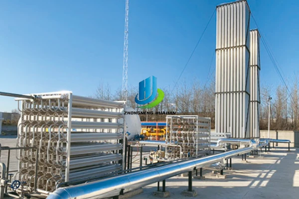
The Frost Map: Reading the Tank's Health
For an operator, the tank's exterior is a diagnostic sheet. A healthy, well-insulated tank will have a consistent, light frost pattern, or maybe just condensation, on its lower half. The appearance of a distinct, hard, vertical frost line is a red alert-it almost certainly indicates a loss of vacuum in a localized section of the insulation annulus. We literally map these frost patterns. I've seen engineers with thermal cameras and notebooks, circling tanks like doctors, diagnosing thermal leaks. The vertical cryogenic tank communicates, if you know how to listen.
Choosing a vertical configuration is rarely a mistake for a large, permanent installation. It represents the optimized center of the engineering Venn diagram: cost, efficiency, construct-ability, and serviceability. It's the grammatical default for a reason. Its ubiquitous presence means a deep pool of trade knowledge, ready-made codes, and predictable performance. It is the quiet, upright, dependable backbone of the industrial gas industry-always there, holding the line between the liquid and the gas, between production and consumption.
Technical Parameters
|
Effective Volume (m³) |
Working Pressure (kPa) |
Overall Dimensions (mm) |
Empty Weight (kg) |
Static Evaporation Rate (%/day) - LOX (Liquid Oxygen) |
Static Evaporation Rate (%/day) - LIN (Liquid Nitrogen) |
Static Evaporation Rate (%/day) - LAR (Liquid Argon) |
|
200 |
8–30 |
Φ 8200 × 12270 |
94000 |
0.32 |
0.50 |
0.34 |
|
300 |
8–30 |
Φ 9800 × 11595 |
120000 |
0.29 |
0.45 |
0.31 |
|
400 |
8–30 |
Φ 9800 × 13680 |
131000 |
0.26 |
0.41 |
0.28 |
|
500 |
8–30 |
Φ 11200 × 12650 |
155000 |
0.25 |
0.39 |
0.27 |
|
600 |
8–30 |
Φ 11200 × 14230 |
163800 |
0.23 |
0.36 |
0.25 |
|
1000 |
8–30 |
Φ 12200 × 17650 |
212300 |
0.19 |
0.30 |
0.20 |
|
1500 |
8–30 |
Φ 14400 × 18270 |
275600 |
0.16 |
0.25 |
0.17 |
|
2000 |
8–30 |
Φ 15700 × 19610 |
330730 |
0.15 |
0.23 |
0.16 |
|
3000 |
8–30 |
Φ 18300 × 20710 |
439270 |
0.13 |
0.20 |
0.14 |
|
4000 |
8–30 |
Φ 20500 × 21620 |
556610 |
0.11 |
0.17 |
0.12 |
|
5000 |
8–30 |
Φ 22300 × 22430 |
645070 |
0.10 |
0.16 |
0.11 |
Hot Tags: vertical cryogenic liquid storage tank, China vertical cryogenic liquid storage tank manufacturers, suppliers, custom process storage tank


